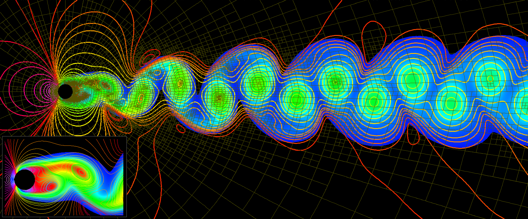
Fluid mechanics is a fascinating field that combines principles of physics and engineering to explore how fluids behave and interact with their surroundings. This course is designed to introduce you to the fundamental concepts and applications of fluid dynamics that are crucial in various engineering disciplines, including mechanical, civil, and chemical engineering.
📌 What You Will Learn:
- Fundamental Principles: Understand the key properties of fluids, including density, viscosity, and pressure, and how these properties influence fluid flow.
- Equations of Fluid Motion: Dive into the core equations such as Bernoulli’s equation, the Continuity equation, and the Navier-Stokes equations, which describe the behavior of fluid flow.
- Real-World Applications: Explore practical applications of fluid mechanics in designing hydraulic systems, aerodynamics, maritime engineering, and environmental management.
📌 Course Features:
- Interactive Lectures: Engage with detailed lectures that include visual aids and real-life case studies to help you grasp complex concepts.
- Hands-On Lab Experiences: Participate in laboratory sessions where you can apply theoretical knowledge to experiments and simulations, enhancing your understanding of fluid behavior.
- Project-Based Learning: Work on group projects that challenge you to solve real-world problems using fluid mechanics principles.
This course is suitable for students who are keen on building a robust foundation in fluid mechanics, as well as professionals who wish to refresh or enhance their knowledge in this critical area of engineering.
1. Fluid Properties and Viscosity
📚 Introduction to Fluid Properties
Fluids, unlike solids, have the ability to flow and conform to the shape of their containers. Key properties of fluids, including specific weight, density, and specific gravity, play a vital role in understanding their behavior in different conditions.
📚 Specific Weight, Density, and Specific Gravity
Specific weight is the weight per unit volume of a fluid, while density is the mass per unit volume. Specific gravity, a dimensionless quantity, is the ratio of the density of the fluid to the density of a reference substance (usually water). Understanding these properties is crucial in applications ranging from buoyancy calculations to fluid transport systems.
💡 Example 1: Calculating Fluid Properties
Calculate the specific weight, density, and specific gravity of one liter of a liquid that weighs 7N.
Specific Weight (γ) = Weight / Volume = 7 N / 0.001 m3 = 7000 N/m3
Density (ρ) = γ / g = 7000 / 9.81 = 713.56 kg/m3
Specific Gravity (SG) = ρ / ρwater = 713.56 / 1000 = 0.713
📚 Understanding Viscosity
Viscosity is a measure of a fluid's resistance to deformation under shear stress. It can be categorized into dynamic viscosity and kinematic viscosity. Dynamic viscosity is a measure of the internal friction of a fluid, while kinematic viscosity is the ratio of dynamic viscosity to the fluid's density. Viscosity plays a crucial role in determining how fluids flow through pipes and around objects, influencing factors like energy loss and flow rate.
💡 Example 2: Determining Fluid Viscosity
A plate 0.025 mm distant from a fixed plate, moves at 60 cm/s and requires a force of 2 N per unit area (2 N/m2) to maintain this speed. Determine the fluid viscosity between the plates.
μ = (2 N/m2) / (60 cm/s / 0.025 mm) = 0.0833 Pa·s
2. Pressure and Fluid Statics
📚 Hydrostatic Pressure
Hydrostatic pressure refers to the pressure exerted by a fluid at rest, primarily due to the force of gravity. The pressure increases with depth and can be calculated using the equation:
Where ρ is the fluid density, g is the acceleration due to gravity, and h is the depth of the fluid. Hydrostatic pressure is a fundamental concept in fluid mechanics, essential for understanding phenomena such as buoyancy, pressure distribution in fluids, and the design of dams and submarines.
💡 Example 3: Manometer Calculation
A manometer is used to measure the pressure in a tank. The fluid has a specific gravity of 0.85, and the manometer column height is 55 cm. If the local atmospheric pressure is 96 kPa, determine the absolute pressure within the tank.
Pabsolute = Pgauge + Patmospheric = 4.579 kPa + 96 kPa = 100.579 kPa
📚 Hydrostatic Force on Submerged Surfaces
The force exerted by a fluid on a submerged surface is known as hydrostatic force. This force acts perpendicular to the surface and can be calculated by integrating the pressure distribution over the area of the surface. The location of the center of pressure, where the total force acts, is also critical in design applications such as gates, dams, and ship hulls.
💡 Example 4: Force on a Rectangular Gate
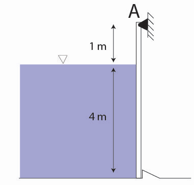
A 5-m-high, 4-m-wide rectangular plate blocks the end of a 4-m-deep freshwater channel. The plate is hinged at its top edge. Calculate the force exerted on the plate by the water.
The hydrostatic force on the gate is 392,400 N.
3. Fluid Dynamics and Flow
📚 Continuity Equation and Flow Analysis
The continuity equation is a fundamental principle in fluid mechanics that expresses the conservation of mass. For incompressible fluid flow, the continuity equation is given by:
Where A is the cross-sectional area and V is the fluid velocity. This equation implies that the product of area and velocity remains constant along a streamline. This principle is crucial in designing piping systems, ducts, and channels to ensure that flow rates are maintained appropriately.
💡 Example 5: Flow Through a Pipe
Water flows through a pipe that tapers from a diameter of 0.2 m to 0.16 m. If the velocity at the inlet is 3 m/s, find the velocity at the outlet.
📚 Bernoulli's Equation
Bernoulli's equation is a principle of fluid dynamics that describes the relationship between the pressure, velocity, and height in a moving fluid. It is derived from the conservation of energy and is expressed as:
Where P is the fluid pressure, ρ is the fluid density, V is the fluid velocity, and h is the height above a reference point. Bernoulli's equation is used to explain various phenomena such as the lift on an airplane wing, the behavior of fluids in pipes, and the design of nozzles and venturimeters.
💡 Example 6: Application of Bernoulli's Equation
A fluid flows through a pipe with varying diameters. If the pressure at a point where the velocity is 3 m/s is 200 kPa, and the pipe diameter changes such that the velocity increases to 5 m/s, determine the pressure at the new section of the pipe.
P2 = P1 + 0.5ρ(V12 - V22)
📚 Acceleration in Fluid Flow
In fluid dynamics, the total acceleration of a fluid particle is the sum of local acceleration (due to the change in velocity with respect to time at a point) and convective acceleration (due to the change in velocity with respect to space). The total acceleration is given by:
Understanding acceleration in fluid flow is essential for analyzing unsteady flows and the behavior of fluid particles in varying velocity fields.
💡 Example 7: Calculating Acceleration in Flow
For a fluid flow where Vx = 5yt2, calculate the local and convective acceleration at point A at t = 0.5 s.
aconvective = Vx * ∂Vx / ∂x = 5yt2 * 5t = 25yt3
4. Pump and Turbine Analysis
📚 Pump Performance
Pumps are devices used to move fluids by mechanical action, typically from lower to higher pressure. The performance of a pump is characterized by its flow rate, head, and efficiency. Pumps are crucial in various engineering systems, including water supply, chemical processing, and oil transportation.
💡 Example 8: Pump Efficiency Calculation
A water pump powered by a 15 kW motor with 90% efficiency delivers water at a flow rate of 0.3 m3/min. If the pressure at the inlet is 100 kPa and the head loss is 3v2/2g, determine the gauge reading.
📚 Turbine Performance
Turbines convert the energy in flowing fluid into mechanical energy. The performance of a turbine is measured by its power output and efficiency. Turbines are essential in power generation, where they convert the energy in steam, water, or wind into electrical energy.
💡 Example 9: Turbine Power Output
A hydraulic power plant operates under certain conditions. If the turbine efficiency is 95%, calculate the output power of the turbine.
5. Advanced Fluid Mechanics Problems
📚 Complex Flow Analysis
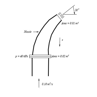
In advanced fluid mechanics, we analyze complex flow situations involving varying geometries, such as bends, nozzles, and venturimeters. These problems often require applying multiple principles, including the continuity equation, Bernoulli’s equation, and energy line analysis.
💡 Example 10: Flow Through a Nozzle
For a nozzle connected to a pipe with known dimensions and flow rate, calculate the new height of the jet and the reaction force on the support.
F = ρQvout
📚 Total Energy Line (T.E.L.) and Hydraulic Grade Line (H.G.L.)
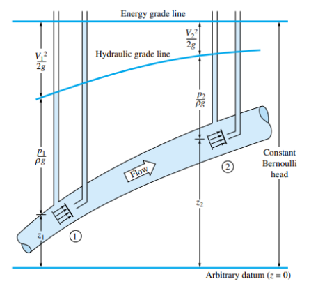
The Total Energy Line (T.E.L.) and Hydraulic Grade Line (H.G.L.) are critical tools in analyzing fluid systems. The T.E.L. represents the total energy per unit weight of the fluid at any point in the system, including kinetic, potential, and pressure energy. The H.G.L. represents the pressure head and elevation head of the fluid.
The T.E.L. is calculated by adding the pressure head (P/ρg), the velocity head (V2/2g), and the elevation head (z). It is expressed as:
The H.G.L. is simply the sum of the pressure head and elevation head, excluding the velocity head:
Understanding and sketching these lines helps in visualizing the energy transformations within a fluid system, identifying potential losses due to friction or other factors, and ensuring that the system operates efficiently. These concepts are fundamental in designing pipelines, water distribution systems, and analyzing open channel flows.
💡 Example 11: Sketching T.E.L. and H.G.L.
For a given fluid system with known pressure, velocity, and elevation at various points, sketch the T.E.L. and H.G.L., considering the head losses and energy transformations along the flow path.
 Exercise sheets
🔹 Sheets:
 Tutorials
 Experiments
-
 Exp.1: Hydrostatic Pressure (link)
 -
 Exp.2: Bernoulli's Theorem (link)
 -
 Exp.3: Energy Loss in Pipe Fittings (link)
 -
 Exp.4: Energy Loss in Pipes (link)
 -
 Exp.5: Impact of a Jet (link)
 -
 Exp.6: Orifice and Free Jet Flow (link)
